More than 50 years’ experience in thermal equipment
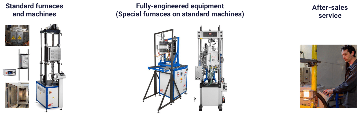
Our expertise includes the integration of multi-brand mechanical testing machines, the design of standard furnaces and machines, the complete engineering of equipment (special furnaces on standard machines), as well as after-sales services tailored to your specific needs. Almost all materials, whether plastics, wood, rubber, concrete, metals, alloys, ceramics or composites, are subjected to mechanical tests to determine their characteristics. These tests are essential to ensure that materials are used optimally in their final applications.
Mechanical tests are experiments designed to characterise the laws of behaviour of materials (continuum mechanics). The behaviour law establishes a relationship between stresses (pressure=force/surface) and strains (dimensionless unit elongation). Deformation should not be confused with displacement or expansion. However, the deformation of a part depends on the geometry of the part and the way in which external forces are exerted on it. Tests must therefore be standardised.
Standards therefore define:
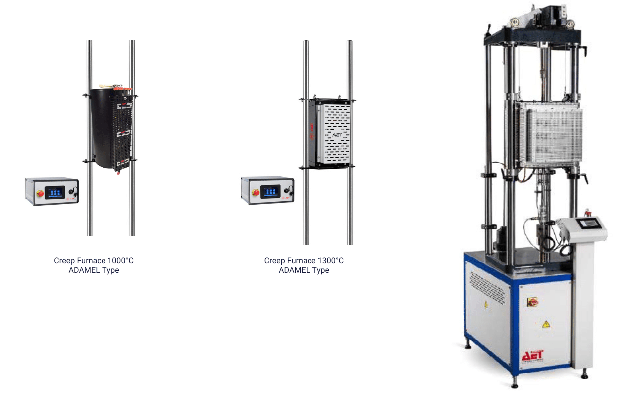
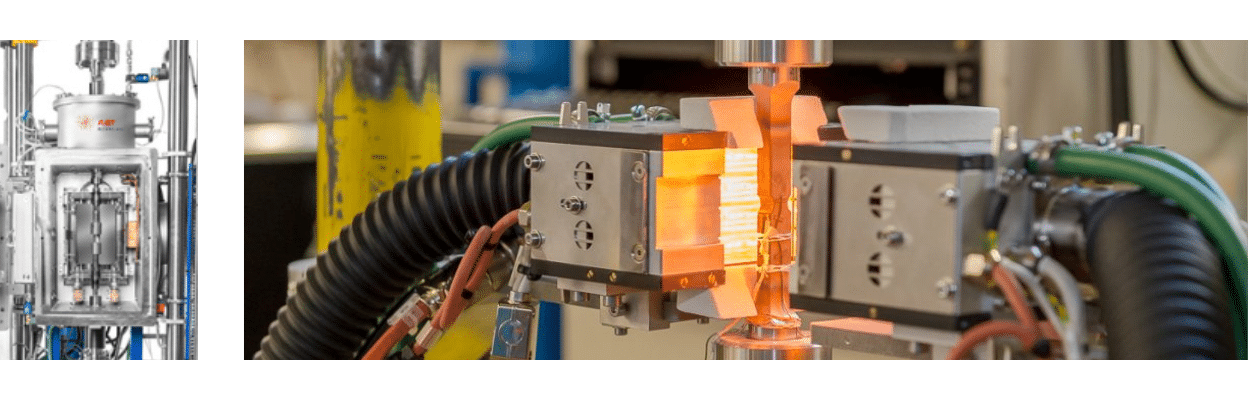
As far as AET Technologies is concerned, the materials you are required to test are subject to various constraints, particularly temperature.
This means that their mechanical properties must be studied under specific thermal conditions, necessitating the integration of an oven into multi-brand mechanical testing machines. This solution makes it possible to test real conditions of use and ensure that the materials will be able to withstand the mechanical and thermal stresses to which they will be exposed.
A tensile test is a physics experiment that measures a material’s breaking strength. Certain manufactured objects must have a minimum level of strength to be able to withstand loads, weight and many other stresses. Tensile testing can be used to characterise materials, regardless of the shape of the object being tested, or the performance of a mechanical assembly. Like all mechanical tests, the tensile test reproduces a simple stress, which is far removed from real stresses, but is easy to control and reproducible. This test or experiment involves placing a small bar of the material under study between the jaws of a tensile testing machine, which pulls on the bar until it breaks. The elongation and force applied are recorded and then converted into deformation and stress.
The tensile test gives several important values:
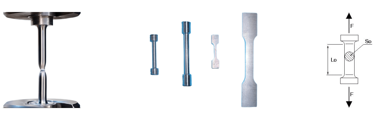
Conventional test tubes with (Do=20 mm, Lo=100 mm) ou (Do=10 mm, Lo=50 mm).
Examples of aluminium alloy tensile specimens.
The specimen is held at two points (by a clamp or hook), connected to wires. The specimen is then stretched at a constant speed, and the tensile force required is determined as a function of elongation. These tests are used to draw a so-called tensile curve, from which the following characteristics can be deduced:
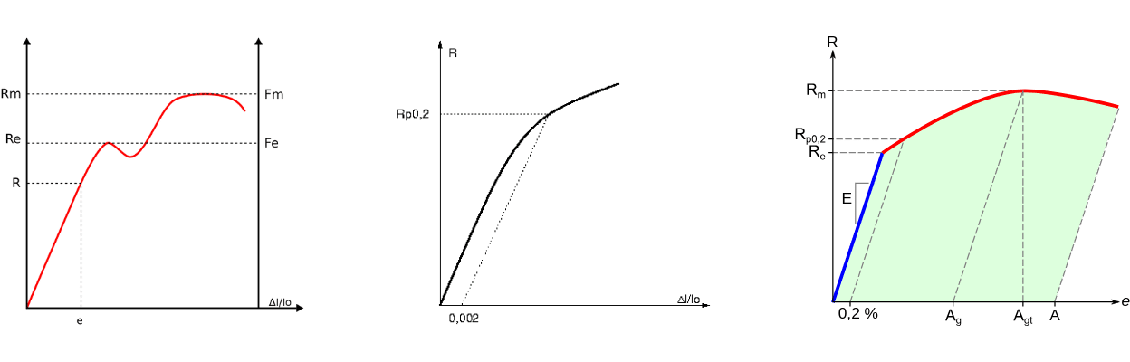
Tensile curve of a ductile material with a step: R stress, F force, Rm maximum stress before rupture, Re apparent elastic limit, e relative elongation, usually noted Ɛ. Conventional test. When it is not possible to determine the apparent yield strength, a conventional limit Rp0.2 is defined, corresponding to a relative elongation e=0.2%.
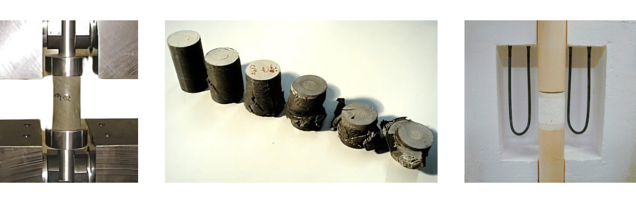
A compression test measures the compressive strength of a material on a mechanical testing machine according to a standard protocol. Compression tests are often carried out on the same machine as tensile tests, but the load is applied in compression instead of tension. During the compression test, the sample is shortened and widened. The relative deformation is “negative” in the sense that the length of the sample decreases. Compression also tends to amplify lateral irregularities in the specimen and, above a critical stress, the specimen may bend and the deflection may increase to the point of buckling.
The specimen is placed between two plates. The test consists of compressing the specimen, often in order to study the breaking force. If the material is ductile, it will not break. In the case of rock, the test is standardised to assess the performance of rock materials in the case of studies of rock structures, for the supply of riprap materials or for the exploitation of granular material deposits. Specimens of slenderness “2” are subjected to vertical compression by imposing an increasing force on the specimen. The specimens are cylindrical.
Fatigue testing consists of applying an alternating variable load (the average of the applied stresses is zero) or a repeated load (the average of the applied stresses is non-zero) to a component. It attempts to reproduce the operating conditions of the part as closely as possible. Fatigue fractures are essentially associated with the total number of load applications and not with the service life or age of the part. Fatigue failure gives no warning before breaking, which is why it can very often surprise the experimenter.
Principle of a fatigue test
Fatigue is a process (a succession of mechanisms) which, under the action of time-varying stresses or strains, modifies the local properties of a material. This can lead to the formation of cracks and eventual failure of the structure. Fatigue is characterised in particular by a range of stress variation that can be well below the material’s elastic limit. The main stages in the fatigue failure of an assembly are crack initiation (if defects are not already present in the material), crack propagation and final failure.
The parameters often used to predict the fatigue behaviour and therefore the number of cycles to failure of a structure are: the amplitude of the stress (loading or imposed deformation), its mean value, the surface finish and the environment in which the structure will be used.
Although the study of fatigue is based on theoretical considerations (in particular fracture mechanics), it is essentially an experimental field. The characterisation of a material, a part, an assembly, a structure, etc. requires numerous tests and measurements.
Bending is the deformation of an object that results in a curvature. In the case of a beam, it tends to bring the two ends of the beam closer together. In the case of a plate, it tends to bring together two points that are diametrically opposed under the action. The beam bending test is a mechanical test used to test bending resistance. Three-point bending and four-point bending are used.
In boiler making, the bending of a sheet is a bend for which the aim is to exceed the elastic limit of the material, in order to obtain a definitive deformation (plastic deformation). In most other cases, however, the aim is to ensure that the elastic limit is not exceeded, in order to preserve the integrity of the part. The bending strength of a material, mainly in the form of a beam, can be measured by a machine under different types of loading. Strain and stress measurements are taken using strain gages and displayed on a measuring bench.
Engineers often wish to understand different aspects of a material’s behaviour, but a simple uniaxial tension or compression test may not provide all the necessary information. When a specimen bends or flexes, it is subjected to a complex combination of forces, including tension, compression and shear. For this reason, bending tests are commonly used to assess the response of materials to realistic loading situations. Bending test data can be particularly useful when a material is to be used as a support structure. For example, a plastic chair needs to provide support in many directions. While the feet are in compression during use, the seat will need to resist the bending forces applied by the person sitting. Not only do manufacturers want to provide a product that can withstand the anticipated loads, but the material must also return to its original shape if bent.
Creep involves tests in which the mechanical and thermal stresses are constant and it is the effects of time that are analysed. The deformation of a material induced during the constant maintenance of temperature and stress is called creep. This deformation is viscoplastic and time-dependent. Although creep is possible at all temperatures above absolute zero, this deformation is thermally activated, meaning that small variations in temperature lead to large variations in the rate of deformation.
For metal alloys, creep is only significant at relatively high temperatures. For example, creep is negligible for alloys used in structures such as bridges or ships. This is not the case for nuclear power station vessels, which have to operate for many years at temperatures in excess of 400°C. Creep can also be significant in the hot parts of gas turbines and turbomachinery for aircraft, where the temperature of some parts is currently as high as 1,100°C. The creep behaviour of type 316 L steels and 800 alloys, for nuclear power plant vessels, or of various nickel-based superalloys, for aircraft turbomachinery, is beginning to be well understood.
Creep must be taken into consideration as soon as the working temperature is close to or above 0.2 Tf (where Tf is the melting temperature of the alloy in question) and/or if there are significant stresses. For example, in the oil industry, creep may not be negligible in cracking units where very high temperatures and stresses may be recorded.
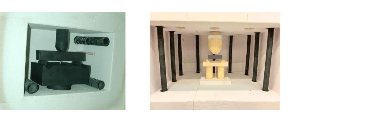
Principle of a creep test
Creep is the physical phenomenon that causes the deferred irreversible deformation (i.e. non-instantaneous) of a material subjected to a constant stress, below the material’s elastic limit, for a sufficient period of time. Creep and stress relaxation are two quasi-static methods for characterising viscous materials (such as concrete).
They are used in particular to test and predict the deformations and degradation of structures (bridges, pre-stressed concrete reactor buildings in nuclear power plants, etc.), which will affect their performance and quality as they age or in the event of a seismic hazard.
In practice, during creep tests, the specimens are usually subjected to a constant force called stress. The stress is then assumed to be constant, provided that the variation in cross-section of the specimen is very small. Stress is defined as the ratio of a force to a surface (i.e. a pressure). Deformation (the response to stress) depends on conditions outside the part: time (t), value of stress, temperature, pressure, etc.
There are two types of mechanical test:
For a viscoelastic material, deformation corresponds to instantaneous elasticity, retarded elasticity and viscous flow. The creep experiment can be monitored by measuring the change in the specimen after the applied stress has been removed. The material has undergone permanent (or residual) deformation linked to irreversible flow. This phenomenon mainly concerns viscoelastic fluids. The longer the period of stress, the greater the permanent deformation.
In the case of a polymer, creep is caused by the sliding of macromolecular chains in relation to each other. To avoid this flow phenomenon, the slippage must be reduced. One solution is to cross-link the polymer, creating covalent bonds between its chains (bridging). The deformation of the viscoelastic solid obtained will be lower than that of the fluid material.